|
installing
a dual battery controller
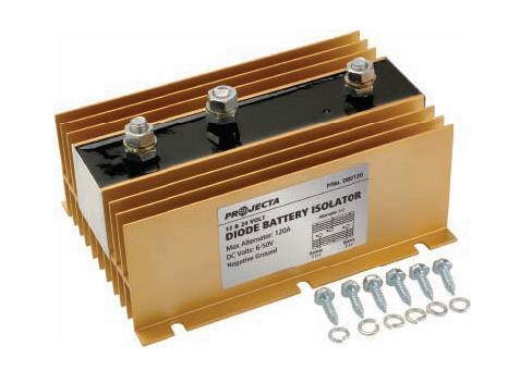
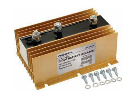
Projecta DBD120
by Grant Jones
I have tried many different dual battery controllers in the
last nine years and always found one problem, in that they all link
the two batteries in parallel once the primary (cranking) battery
has been fully charged (according to the controller).
First one that I
installed was a Piranha BDE150s and it was not a bad unit but after
two years it went into self destruct mode so I consigned it to my
File 13 (bin).
Next was a neat
little solid state unit from 4WD systems fitted well but died (fried
itself) after about 18 months, so once again file 13 was utilized.
My third try was
a very good unit from ABR Sidewinder DBI 120 this worked very well
but I was always finding not enough juice in second battery to run
accessories (fridge) for more than a few hours (a real pain in the
proverbial). I also found that when doing voltage checks on both
batteries that neither were receiving a full charge, so I figured I
would have to go with a 12v to 12v charger as well. Batteries were
being charged to 12.49 volts only (not a full charge according to
R&J Batteries in Ballarat)
Roughly 12 months ago I started looking and reading all I
could find on all dual battery controllers, biggest problem with
them was they all connected both batteries in parallel, not what I
wanted. I did find one quite by chance it is made by Projecta and
kept both batteries separate at all times. Now I was starting to get
somewhere but first I had to find out if my alternator was
externally sensed, so out with the bible and more reading, and to my
delight it was externally sensed.
Having ordered the controller (Projecta DBD 120) I waited for
it to arrive with some impatience and also trepidation as the
dimensions on their web site make it look enormous (165mm long,
114mm wide and 83mm high). When it finally arrived and I took it out
of the box the damn thing was massive, now where in the hell am I
going to fit this monster (I know throw out second battery and mount
it to the tray).
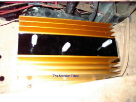
Looking for a
space to fit this 1.3kg piece of electronics, I finally settled on a
space inside the bull bar, which was just big enough and it would
also be well protected, away from any engine heat and relatively
easy to get at. Mind you if you remove the heat sink it is not very
big, but the heat sink is there for a reason.
First thing first!
Follow the instructions to get voltage readings off the charging
system.
• Cranking battery standing voltage 12.49 volts (after sitting
overnight)
• With the engine running and all accessories turned of voltage
output at the main battery was 13.67 volts
• With engine running and all accessories, including lights turned
on voltage at the battery was 13.68 volts. (you need a minimum
voltage of 13.6 volts)
I dragged out my setting saver unit (9 volt battery connected
to cigarette light plug) fitted a new 9 volt battery (plugs into
cigarette lighter plug) to save having to reset the radio (Kenwood)
then making sure that ignition turned to accessory (note turn off
all that accessories first),
• I pulled out both batteries giving me room to see and trace the
existing wiring.
• After disconnecting the output wire from the alternator I moved it
out of the road and fed the conduit with the three new wires into
place.
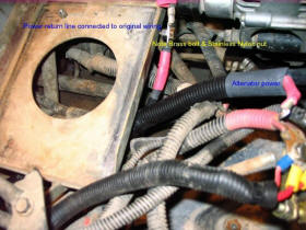
• Having already soldered the terminals onto the new wires (I do not
trust crimp joints), I could slip the heat shrink over the wire to
be connected to the original wiring
• Using a ¼ inch Brass bolt I joined the new wire onto the existing
alternator output wire along then used three layers of heat shrink
to give a good weatherproof join
• After the heat shrink I, connected the new alternator output wire
to the alternator and fitting all the tubing into place securing it
along the way with cable ties
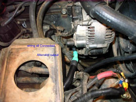
• Next it was under the front of the JEEP and sort out the wires and
get them connected and tidied up which was fairly simple
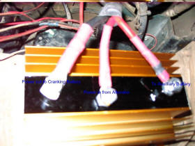
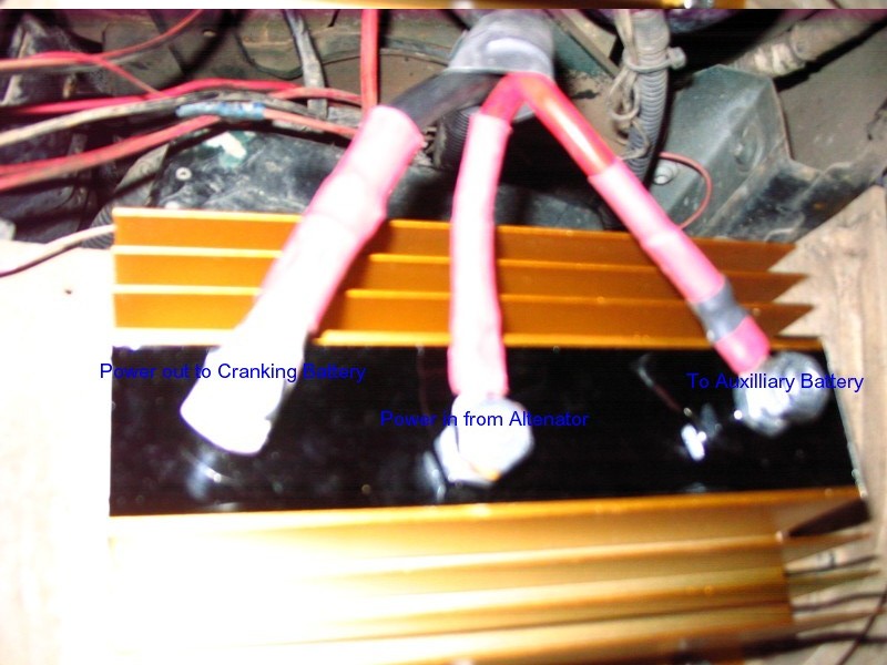
• 3 wires, centre one is input from alternator, left one is return
line into existing power circuit, and the Right hand line goes to
auxiliary battery.
Now for the fun after having refitted both batteries and
gotten rid of my settings saver, it was time to crank things up
(right after some checks). It was time for the multi meter again.
• Main battery read at alternator (engine turned off) 12.44 volts
(0.05 voltage drop acceptable) at auxiliary 13.20 volts.
• With engine running at idle and accessories off reading at main
battery 13.98 volts, auxiliary battery 14.10 volts
• Fast idle (2000 rpm) all accessories turned off, main battery
14.01 volts, auxiliary 14.15 volts
• With everything turned on with engine still at 2000 rpm (including
all driving lights, electric fans, air conditioner and all radios)
reading at main battery 13.95 volts, at auxiliary battery
14.20volts.
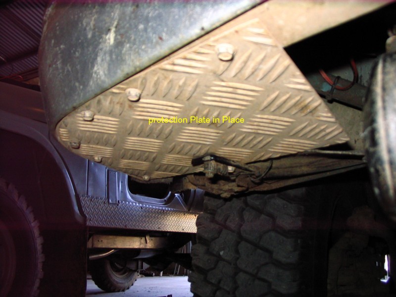
All neatly hidden up under a
protection plate

I hope the above information helps people out
thanks to Grant for sharing this idea
april 2011
|